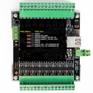
1. Getting Started
Thank you for purchasing our Flexs Q4!
Below we’ve outlined a few quick steps to help you get started with your new device.
Quick Start Instructions
Step 1. Power The Device
- Your Flexs Q4 is powered by the Screw Terminal located directly beside the network jack.
- The power supply input is Reverse Polarity Protected but will not operate unless connected correctly, correct polarity is labeled on the board.
- The Flexs Q4 requires a DC Input Voltage that is between 8 and 30 volts and capable of supplying at least 2 watts, do not exceed the maximum voltage rating.
Step 2. Connect the Network Jack to your computer or network
- Any Network cable can be used, the Flexs Q4 will automatically correct for crossover type cables.
- Your computer must have a static ip if you are connecting it directly to the Q4, if you are connecting the Q4 to a router or network you can ignore this as DHCP will be used.
Step 3. Connect to the Flexs Q4
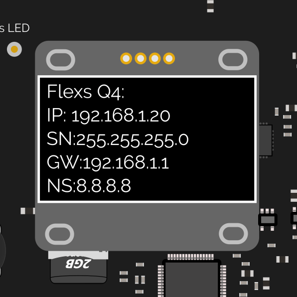
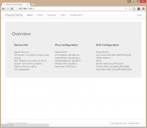
- Using a web browser open the IP address shown on the devices LCD display panel, e.g. http://192.168.1.20 (Below Example)
Step 4. Configure the Device
- After you connect to the device with your web browser you will see 5 tabs, Each tab’s function is outlined below
- Status tab displays system uptime, network and version info.
- Feeds tab displays the voltages at each of the eight analog inputs and allows you to control the relay outputs.
- Graphing tab allows you to plot the analog input voltages or relay output states over time.
- Logic tab is where you configure the devices onboard logic, simple expressions can be setup to alter the state of an output based on the value of an input or timer.
- Configuration tab. This is where you label your inputs and outputs, setup default output states, configure network settings and more!
Default Device Configuration:
Input/Output:
- Analog Input Mode: Voltage Mode, Max +/- 60 volts
- Relay Outputs: Default state is OFF for all eight outputs
Networking:
- IPV4: DHCP with a fallback address of 192.168.1.20
- IPV6: SLAAC with a fallback address of fe80::33:b0ff:fec5:506
- Username / Password: disabled by default, no login required
- Hostname: Q35325234321 (Number will change for each device but will always start with a ‘Q’)
Contact Info
2. Updating the firmware
After receiving your Flexs Q4 we recommend you update to the latest firmware.
Upgrading the firmware on the Flexs is completely safe and even if the upgrade fails half way through due to power or network loss, your device will not be damaged, it will simply reboot into it’s firmware update mode until a firmware is successful loaded.
NOTE: In order to update the firmware the Flexs Q4 must be connected to the internet.
Step 1.
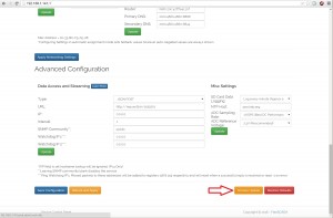
Click on the configuration tab and scroll to the bottom of the page, on the right corner you’ll see a button labeled ‘Update Firmware’
Click the ‘Update Firmware’ button and reload the web page (It may take several minuets before the page will reload)
Step 2.
After reloading the page your device will be in Firmware Update Mode.
Click the update button to the right of the URL text box as shown in the photo, only click the button once and wait about a minute (Depends on internet speed)
Step 3.
Reload the web page and your Flexs Q4 will be running the latest firmware
Troubleshooting:
LCD Not running in DFU mode
The LCD driver is not designed to run while the device is operating in DFU mode
Device always boots into DFU (Firmware Update) mode:
Ensure the Flexs Q4 is connected to the internet and repeat the firmware update steps carefully.
Contact us if you are unable to resolve this issue
Device never enters DFU mode
The Flexs Q4 will automatically exit DFU mode after 1 minute if no firmware update was initiated, please repeat the steps again ensuring that you reload the page shortly after clicking the ‘Firmware Update’ button.
On some early models of the Flexs Q4 the device may use a different MAC address when in DFU mode which could result in the Flexs Q4 obtaining a different IP than expected if dhcp is used, if the Flexs Q4 goes offline after attempting to enter DFU mode consider changing the network configurations to utilize a Static IP Address, in some cases it may also be necessary to flush the arp cache on your router before entering dfu mode.
Force the Flexs Q4 to enter DFU mode:
Unplug the power from the Flexs Q4
Press ‘IN’ on the encoder knob (It should click) and hold it down while plugging the power back in
Connect to the Flexs Q4 and proceed with the update normally, the device should be in DFU mode http://comcomservices.ca/firmwares/beta.bin
Changelog:
V8.1 (Built on May 12 2017) **Beta Firmware (Please change the update url to http://comcomservices.ca/firmwares/beta.bin before clicking update after entering DFU mode)
- Improved functionality of onboard OLED display for local personal interfacing.
- New Oscilloscope function for troubleshooting noisy power systems
- More readable fonts
- Network status page now shows whether DHCP is enabled
- Reduced power consumption on latest hardware
V8.0 (Built on September 7, 2016)
- Full SDHC Card support (Up to 128GB)
- DHCP Server removes the need for setting a manual ip during initial configuration
- New Power Saving Features
- Low Power Mode (0.5W Power Consumption*)
- Medium Power Mode (0.65W Power Consumption*)
- High Power Mode (0.9W Power Consumption*)
- *measured at 12VDC
V7.0 (Built on march 8, 2016) **Latest Stable version
- Web UI improvements including context help and better mobile support
- Updated IP stack allows more users to connect simultaneously.
- New logic rules for threshold based control.
V6.2 (Built on Dec 14)
- Improved LCD functionality
- Web UI improvements
- Relay Switches are driven to their default states during firmware upgrades instead being turned off **Requires boot-loader version 6.2 or later as-well
V6.0 (Built on October 29)
- Adds ‘Pulse Counter’ input mode, keeps accumulating count of pulses on any input channel
- Adds ‘Pulses / Second’ input mode, tracks pulses per second
- Adds ‘HZ (Peroid)’ input mode, Tracks input frequency based on waveform period
- Adds ‘1S Averaged’ input mode, Averages input values over a 1 second period
- New Oscilloscope now shows stacked waveform’s for all 8 input channels
- CRC Detection and Verification on DS18b20 one wire temperature sensors
- Improved resolution on JSON streaming mode (8 digits of precision)
- Improved AC Vector calculation resolution, vectors now calculated in sync with phase when stream period < 5s
- AC Line Frequency always calculated on first feed voltage source, result in register #47
V5.6 (Built on October 13)
- Changes to SNMP OID’s to fix compatibility issues with SolarWinds SAM
- Added ‘Logic Priority’ option to configuration tab, allows you to manually specify the priority of the onboard logic task for a snappier web interface
V5.5.1 (Built on Sep 26)
- Adds ‘getreg’ http command to list of TCP methods, Example = http://192.168.1.133/cmd.shtm?cmd=getreg®=1 to get the value of register 1
- Updates ‘setreg’ http command to return the register value after setting it Example = http://192.168.1.133/cmd.shtm?cmd=setreg®=1=9&val=1 to set register 9 (relay 1) to 1 (on)
V5.5 (Built on Sep 24 2015)
- Improved SNMP Support
V5.3 (Built on Sep 22 2015)
- NOTE: Upgrading to this firmware may change the MAC address of your device under some circumstances, please remember this if you are using DHCP to access your device as it may obtain a new IP address after the update process
- UI: Fixes issue where default output state could not be set for load switch ch1
- NETWORK: Fixed DHCP Fallback IPv4 Address, Under certain circumstances the Flexs Q4 would fail to be reachable at it’s fallback IPv4 address when used without a dhcp server in dhcp mode
- GENERAL: Reboots are no longer required when modifying device configuration settings
- GNENERAL: Delay when entering DFU mode for firmware upgrade has been removed allowing for more convenient upgrades
V5.2 (Built on Sep 17 2015)
- Stability fix, under heavy DDOS attacks it was reported that the device would occasionally reset, the problem was traced to a watchdog not being serviced in a timely manner and has been resolved.
- Setting NTP server to blank now disables the service, prevents spamming of LOG when the device is used without an internet connection
- LCD Interface now supports viewing analog input values, load switch sates, network settings and registers
V5.0 (Built on Sep 14 2015)
- Fixes stability issue when using DS18B20 one wire temperature sensors
- Easier Configuration, Device reboots no longer required to apply settings
- General Software UI improvements
- Fixes to password configuration method, reduces confusion
- Adds Record to SD card when remote endpoint down
V4.3 (Built on Sep 9 2015) **Upgrading to this firmware will reset configuration settings, network settings will be left intact.
- Adds SD Card (Logging and custom webpage support)
- Adds One Wire DS18b20 Support
- Adds Oscilloscope tab with FFT support
- Adds SNMP Support
- Adds ping based relay control
- Adds option to manually specify SNTP server
- Improved graphing tab
- Improved Registers tab (Adds labels and live updating)
- Fixes HTTP JSON Post random timeout issue
V4.2
- Initial Public Release
3. Analog Inputs
The Flexs Q4 features Eight universal analog inputs that can be used to connect to a wide variety of sensors.
It won’t be possible to cover every possible sensor that the Flexs Q4 can monitor but we will go over several common types.
DC Voltage
The Flexs Q4’s analog inputs can measure DC voltage up to 60V (Negative or Positive)
Let’s go over the steps to monitor battery voltage on input channel #2
Step 1
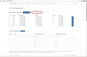
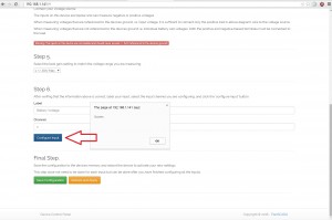
Start by clicking on the ‘Configuration Wizzard’ button from the configuration tab as shown below
Step 2.
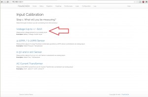
Select the ‘DC Voltage’ option from the wizards list of options.
Step 3.
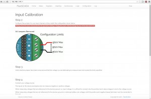
Follow the steps outlined in the wizard including removing any mode jumpers from the board.
Step 4.
Finish following the steps outlined, step 5 allows you to configure the on-board gain amplifier to best suit the voltage of the signal you are measuring. I.E. if you are measuring a voltage that’s never going to be above 2V, you could select the highest gain setting for maximum resolution
Label the input channel and select the channel you are configuring, in our case #2
Label: Battery Voltage
Channel: 2
Click the ‘Apply Configuration’ button
Click the ‘Save Configuration’ button
Step 5. Test
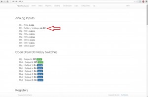
Open the registers tab and you should see the battery voltage displayed as shown below
4-20MA Sensors
4-20ma sensors come in two types, Loop Powered and Externally Powered, Loop powered sensors are the most common and our powered through the same wires that transmit the sensor’s value (signal)
Oscilloscope
The Oscilloscope is useful for a variety of reasons
- Analyzing the noise level in a dc power system
- Analyzing the output from vibration or acceleration type sensors
- Analyzing the AC waveform from AC Current Transformers or Voltage transformers
- Troubleshooting bad sensor readings
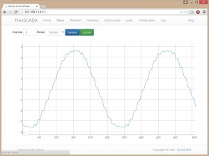
To open the oscilloscope, click on the ‘Oscilloscope’ tab and enter the analog input channel you would like to view
Clicking the sample button saves the waveform to a buffer on the device until the next sample comes in.
Clicking the Update button renders the waveform saved in the buffer to the screen
There is also an FFT mode for more detailed harmonic analysis, The FFT output is 256 points and it’s frequency can be calculated by the ADC Sampling Rate.
4. Load Switches
The Flexs Q4 comes in two variants which are both used to operate different types of loads
Model 8IS: 8X Solid State DC Relays
Each of the eight solid state DC relay switches are completely isolated and have the following specifications:
Max Voltage: 60V
Max Current: 10A (50A <1ms)
Switching Speed: typ < 8ms
Connection polarity is specified on the board, if not followed no damage will occur however the load switch will appear to be always on if connected wrongly, always confirm operation before leaving an installation site.
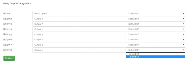
Each of the solid state relays can be configured to accept a fixed state on power up and a label for easy referencing.
Model 4L: 4X Mechanical Latching Relays
Each of the 4 latching relays are rated to switch AC Loads at up to 250V / 15A or DC Loads at up to 250V / 8A and are highly reliable by utilizing two contacts in parallel operation. Since the relays are latching they consume zero power regardless of state making them ideally suited for low power off grid operation.
Each relay can be configured to accept a fixed state on powerup or continue to hold the currently latched value, an overview of the configuration tab for the relay model is shown below. A name can also be specified which allows for easy in person control from the onboard LCD display.
5. Registers & Logic
The Flexs Q4 features 128 registers that are used to read and set everything on the device including
- Voltages at each of the analog inputs
- Load Switch states
- Calculated Vectors (Vrms, Lrms, PF)
- One Wire Temp Sensor values
- Date and time
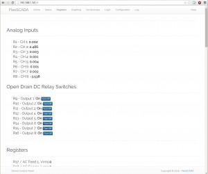
The ‘Registers’ tab allows you to view the values at each of the 128 registers.
As you can see in the above photo, registers 1-8 contain the value of each of the analog inputs, registers 9-17 contain the values of the load switches.
6. Getting Sensor Data from the device
SNMP
Registers can be polled via SNMP Version 1
The SNMP community is modified on the ‘Configuration’ tab and optionally can be set blank to disable the snmp service.
Values returned via SNMP are of a string type and contain the exact register value to 4 decimal places.
To get the voltage on input channel 2 (register #2) the following command can be used.
snmpget -v1 -c "public" 162.216.184.183 1.3.6.1.4.1.4128.2
iso.3.6.1.4.1.4128.1 = STRING: "12.9867"
To get the status of relay output 1 (register #9) the following command can be used.
snmpget -v1 -c "public" 162.216.184.183 1.3.6.1.4.1.4128.9
iso.3.6.1.4.1.4128.9 = STRING: "1"
UDP Streaming
Data can be streamed via UDP from the Flexs Q4 device when enabled on the ‘Configuration’ tab.
Data is returned in a packed struct of the following composition.
typedef struct Registers
{
uint64_t uid; // 64bit uuid of device
char hash[32];// SHA256 hash of data + password + uid
float data[128]; //register data
}
JSON HTTP Requests
The Flexs Q4 can post sensor data to your server through an HTTP POST request.
To enable this feature select the streaming mode: ‘HTTP/JSON POST’ from the ‘Configuration’ tab / Streaming Section
EXAMPLE POST DATA:
{
"uid":3249352961,
"registers":[0,0.0018,13,0.0033,0.001,0.0043,0.00092,0.0011,-3.1,0,0,1,1,1,1,1,1,0,0,0,0,0,0,0,0,0,0,0,0,0,0,0,0,0,0,0,0,0,0,0,0,0,0,0,0,0,0,0,4,23,23,34,30,0,0,0,0,0,0,0,0,0,0,0,0,0,0,0,0,0,0,0,0,0,0,0,0,0,0,0,0,0,0,0,0,0,0,0,0,0,0,0,0,0,0,0,0,0,0,0,0,0,0,0,0,0,0,0,0,0,0,0,0,0,0,0,0,0,0,0,6.4e+03,21,22,5,9,9,3.9e+04,1e+03] "registers":[0,0.0018,13,0.0033,0.001,0.0043,0.00092,0.0011,-3.1,0,0,1,1,1,1,1,1,0,0,0,0,0,0,0,0,0,0,0,0,0,0,0,0,0,0,0,0,0,0,0,0,0,0,0,0,0,0,0,4,23,23,34,30,0,0,0,0,0,0,0,0,0,0,0,0,0,0,0,0,0,0,0,0,0,0,0,0,0,0,0,0,0,0,0,0,0,0,0,0,0,0,0,0,0,0,0,0,0,0,0,0,0,0,0,0,0,0,0,0,0,0,0,0,0,0,0,0,0,0,0,6.4e+03,21,22,5,9,9,3.9e+04,1e+03]
}
Example PHP Listener script which logs the value of analog input channel 1 (register 1) to a text file on the server named log.txt
<?php
$json = json_decode ( file_get_contents("php://input"));
$fh = fopen("log.txt", 'a') or die("can't open file");
fwrite($fh, $json->registers[1] . "n");
?>
7. Custom Web Pages
Custom web pages can be created for the Flexs Q4 by creating an index.htm file on an SD card and inserting it into the devices SD card socket
Several tags can be used to visualize the register values dynamically on your page.
Examples:
Display value of register #1 (Analog Input 1)
Battery Voltage: <b reg=1></b><b> Volts</b><br>
Switch Widget for Register #9 (Load Switch #1)
Load Relay 1: <r class=sw reg=9></r><br>
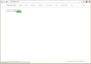
Example index.htm file that shows voltage on channel 1 and allows you to toggle load switch #2
The values on this page are also updated automatically every second
Channel 1 Voltage: <b reg=1></b>
<br>
Channel 1 Load Relay: <r class=sw reg=9></r>


<script>
updateRegisters(); // Update the registers values on the page

// Create a timer to automatically update the register values on the page every 1000ms (1 second)

// The timer VAR is already declared by the API so we just set it to our timer
timer = setInterval(function(){updateRegisters()},1000);

</script>
Saving this script to a file called index.htm will create a ‘Home’ tab for the web interface that will load your file
Jquery, Dygraphs and Bootstrap are available locally on the device for creating more advanced pages.
8. One Wire Temp Sensors
The Flexs Q4 allows you to connect up to 16 digital ds18b20 temp sensors all sharing the same three wires.
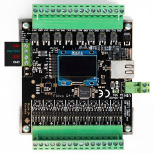
One Wire sensors are connected to the 4 pin screw terminal opposite the network connector.
VCC -> 3.3V
One Wire -> One Wire
GND -> GND
After connecting your sensors you must reboot or save/apply settings on the device so your sensors can be detected, the temperatures from each sensor will show up starting at register #49 and continuing upwards with one register for each sensor.
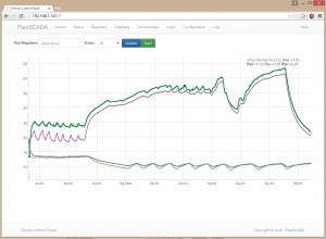
Shown here is a graph of temperatures from 4 one wire DS18B20 sensors (Registers #49, #50, #51, #52)
One wire sensors are updated / read at the same interval as the ‘Stream Interval’ option on the configuration tab
9. Misc Settings
SD Card Data Logging
The Flexs Q4 offers several data logging modes, these modes are configurable via a dropdown on the ‘Configuration’ tab under the Misc Settings settings
Data Logging Modes:
- Disabled: No Data Logging
- Every Minute: Registers are logged to the SD Card in CSV format with a time-stamp every minute, this mode uses approximately 1GB of storage per year
- Every 5 Minutes: Registers are logged every 5 minutes, this mode uses approximately 200MB’s of storage per year
- Every Hour: This mode uses approximately 16MB per year
- Unreachable: Registers are logged to the SD Card when A. streaming is enabled and B. the streaming endpoint is unreachable, if UDP streaming is used, the endpoint status is determined by the result of the DNS query which may be cached in your network which could delay or impair operation of this mechanism
The CSV file created by the data logger can be imported into Excel or similar spreadsheet programs but keep in mind that large files may be very slow to work with so always choose the longest logging interval required for your application.
Internet Time
By default the Flexs Q4 will detect if it has lost it’s time and automatically sync with the NTP server specified on the ‘Configuration’ tab.
Time is lost whenever the Flexs Q4 looses power but not during a reboot, for this reason it is recommended to power the Flexs Q4 from a battery or UPS
ADC
The ADC Sampling Rate determines how many times per second the voltages on each input are updated.
When measuring slowly changing sources such as battery voltage a low sampling rate is recommended for maximum input filtering.
When measuring rapidly changing sources such as vibration sensors, ac current or ac voltage a higher sampling rate is recommended such as 4ksps to 16ksps depending on the bandwidth requirements of your application.
I.E. if you want to monitor vibration on a 3600RPM motor your sampling rate should be at least 8KSPS
ADC Reference Voltage
This is for advanced usage only, for normal use always keep the ADC reference voltage set at 2.4V
Power Saving Modes
Even with no power saving enabled the Flexs Q4 is incredibly power efficient using just under a watt however for some extremely remote installations where solar panels may be obstructed for long periods of time or where only minimal battery storage is available the Flexs Q4 has 3 options to further reduce power.
- Aggressive
- Restricts Ethernet interface to 10M/10M Max Data Rate by altering it’s advertised abilities
- Reduces cpu clock rate slowing down the web interface and limiting the ADC sample rate to 2KSPS MAX
- Power Consumption is reduced to approximately 0.5W (All relays OFF)
- Medium
- Reduces cpu clock rate slowing down the responsiveness of the onboard web interface and limiting the max ADC Sample rate to 4KSPS
- Power Consumption is reduced to approximately 0.7W (All relays OFF)
- None
- No Power Reduction, CPU operates at full speed with no limitations
- Power consumption is approximately 0.85W (All relays OFF)
- Default Setting
9. Resetting the Flexs Q4 to default settings
There are two methods to reset the settings on your Flexs Q4
A. Click the ‘Restore Defaults’ button at the bottom right of the ‘Configuration’ tab
B. Unplug power to the Flexs Q4, Press ‘IN’ on the encoder knob (It should click), Hold down this button while re-plugging the devices power and hold it for an additional 45 seconds, the settings will be erased to defaults
10. HTTP API
The Flexs Q4 features a basic HTTP API that can be used to query the analog input values and set the relay output states.
Note to developers: (All of the interface configuration elements are configurable through http calls as well, contact us for documentation or refer to your browsers web inspector)
HTTP API Commands:
11. Setting Device Registers via UDP
The Flexs Q4 listens for setreg commands on port 8001, To remove the need for port forwarding a reply can be made to an outgoing udp stream packet from the device.
Basic Concept:
A struct is created containing the register we are attempting to set, and the value we are setting the register to, additionally an uptime field is added to ensure that the commands can only be used within a timely manner.
After populating these fields the plaintext password of the device is copied to the ‘hash’ field of this struct, next a sha256 hash is then computed on the entire structure and finally the computed sha256 hash is then copied back to the hash field replacing the plaintext password it had earlier.
Please note, to use the UDP set reg command, a password MUST be set on the device.
#pragma pack(1)

typedef struct
{
    unsigned char hash[32];
    uint32_t reg;
    float value;
    uint32_t uptime;
} WREG;
#pragma push


WREG wreg_pckt;
char *device_password = "testest";
wreg_pckt.reg = 9;                      // Relay 1
wreg_pckt.value = 1;                    // Set register 9, (Relay 1) to 1 (on)
wreg_pckt.uptime = registers.data[120]; // this field must be within +/-600 seconds of the devices uptime register (reg 120)
                                        // For this reason setreg commands are nearly always a response to a received register stream packet from the device (This is a security measure to ensure a packed cannot be cached by a man in the middle and reinjected)

strncpy(wreg_pckt.hash,device_password,sizeof(wreg_pckt.hash)); // Copy the password string into the packet, we use the strNcpy command to ensure that if the password is longer than 32 characters, we do not overflow the buffer

char hash[32]; // Create a temporary container to store the hash of our packet
SHA256::computeHash(hash, (uint8_t*)&wreg_pckt, sizeof(wreg_pckt));

memcpy(wreg_pckt.hash,hash,sizeof(wreg_pckt.hash)); // Now we will set the packets hash field with our computed sha256 hash

/// Not shown, send wreg_pckt via UDP to the endpoints ip address on port 8001
11. Expansion Header (API users)
The Flexs Q4 features an expansion header for connecting with external peripherals.
The expansion header features 6 GPIO pins and also contains a High Speed UART, SPI bus and I2C Bus
For debugging purposes a computer can be connected to the PC Console TX and RX pins with a TTL -> USB adapter
Serial Port settings are 115200 baud, 8N1
12. Using the ping watchdog timers to automatically reboot devices
The Flexs Q4 features two independent ping watchdog counters which can be used to toggle relays after excessive loss is detected.
In this guide we will quickly go over the steps used to reboot a device connected to relay 1 after 5 consecutive missed packets.
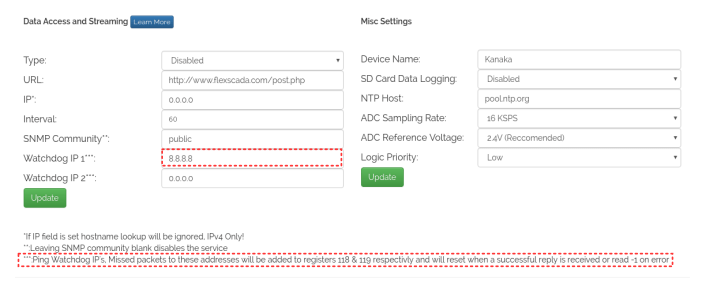
Step 1. Scroll to the bottom of the configuration page and input the devices IP address into the ‘Watchdog IP 1’ field (Highlighted in below photo)
The specified devices ip address will be pinged according to the ‘Interval’ field which is in seconds.
Step 2. Create the logic rules which reflect the following photographs
The pinger we setup previously outputted the number of missed packets to register 118.
Rule line 1 ‘PING WD’ sets register 100 to ‘1’ for 2 seconds (Deactivation delay) after each 5 consecutive missed packets.
Rule line 2 ‘WD CTRL’ sets relay 1 (register 9) to the inverted value of register 100 (Temporary holding register)
Note: If the ethernet link to the Q4 is physically disconnected relay 1 will always stay in the ON state.
That’s it! You’re ready to start monitoring your devices and rebooting them automatically if they go unreachable.

