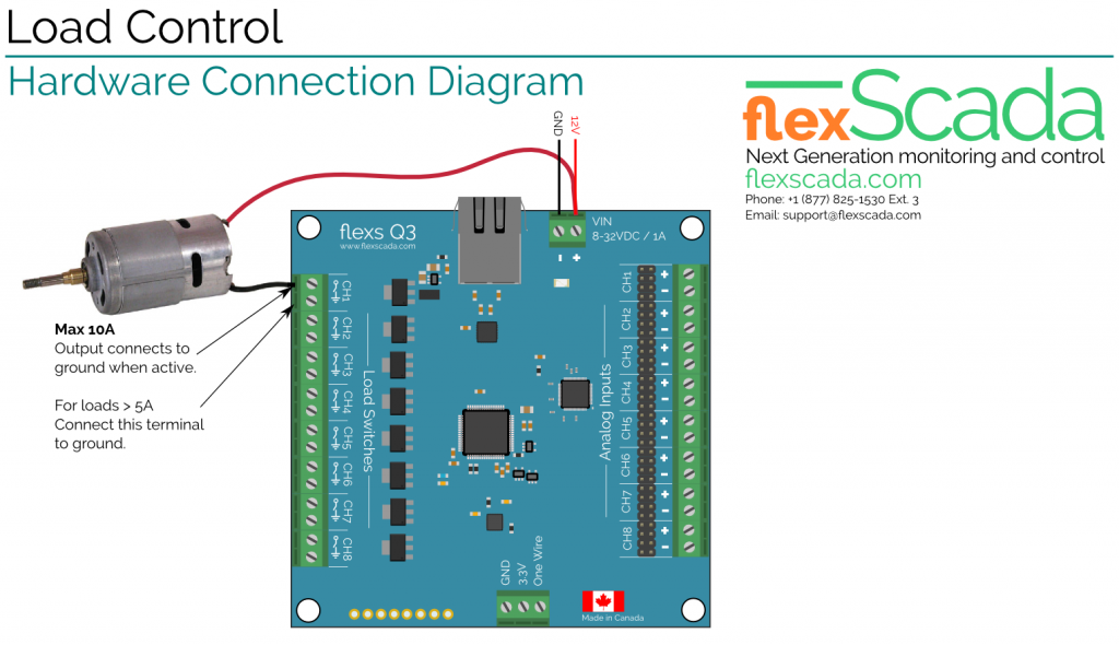
Turning loads on and off remotely using the Flexs Q3’s On-board Relays

The Flexs Q3 Smart PLC has 8 Universal Analog Inputs and 8 solid state dc load switches.
The solid state relays allow for nearly instantaneous response time and use no electricity whether activated or deactivated.
To allow for switching loads operating at different supply voltages the Flexs Q3 utilizes industry standard Open-Drain outputs, Open-Drain means the switch is on the negative side of the load as shown in our example – when the relay is activated (ON) the output is grounded energizing the load, when the relay is not activated (OFF) the output floats at the supply voltage not allowing any current to flow through the load.
The 8 Load switches on the device each have two terminals, the output terminal and a ground terminal, for small loads (<5A) the ground terminal can be left disconnected and the current will flow through the main device ground, for larger loads the ground terminal on the output should be connected to reduce the risk of exceeding the rated current on the main supply terminal.
Logic:
Using the onboard EZ-Logic expressions can be easily setup to activate or deactivate the onboard relay outputs based on the voltage, current, pressure (when using a sensor), frequency etc. at any of the input channels.
For a simple usage example lets set up an expression that activates output channel #1 whenever the voltage on input channel #1 is greater then 11.9V
On the left column we give the expression a name ‘Webcam Off’, next we have the ‘type’ since were comparing a register with a value we select ‘Register: Value’ which means compare the value of register X with the value we specify.
In the ‘Reg’ column enter the register number that holds the result of input channel #1 (This can be found from the ‘Registers’ tab as shown below, register # is on the far left next to the name)
In the next column of our logic expression we select the logic operator, since we want the output to be on whenever the voltage is ‘Greater’ then a set value we select the ‘Greater’ operator designated with the ‘>’ icon
Finally we enter the value that were comparing our voltage to into the ‘Value/Reg’ column and enter the register # where we want the result of the expression to be placed into the ‘Dest Reg’ column (#27 for output channel 1, see image below).
To complete our logic expression enter 10 seconds into the ‘Activate Delay’ column, this insures that the output dosn’t cycle rapidly while the voltage is hovering close to the threshold…
That’s it! the value of our expression automatically determines the status of our relay output! Instead of an expression based on voltage we could also be comparing with a register containing the current Hour or Day to configure a load to come on at set times! It’s super easy and very flexible!
Final Logic Breakdown: If Register #1 (Contains CH1 Voltage) is ‘Greater’ than 11.9V for 10 seconds, set register #27 (Relay Output #1) High, otherwise set Output Low
Controlling Large AC or DC Loads
Controlling larger DC or AC loads can be accomplished by using the onboard relays to trigger a larger external Mechanical or Solid State relay.
Technical Specs:
- Channels:8
- Surge Rating: 50A <1ms
- Max Current: 8A (continous)
- Max Voltage: 31V (exceeding this voltage will begin to energize the relay and is not recommended)
- Power Consumption (ON): 0.000w
- Power Consumption (OFF): 0.000w
- Response Time: <0.1ms
- Rated Lifetime: >10 billion cycles, >10years @ 30c
- Type: N-Channel Logic Level Mosfet
- Isolation: None, DC Only!


