Using the Flexs Q3 Configuration Software
Please begin by downloading the Quick Start Guide (Html) (Pdf)
After following the steps in the quick start guide and connecting to the device with the configuration assistant we’re going to setup a simple logic expression that activates output channel 1 when the voltage at an input exceeds a set threshold.
But first some basics..
The Flexs device family utilizes what we call the “registry”, basically it’s a series of values used to store and access the results of the Analog Inputs, Output Statuses, Etc, each value has a index number that’s used to reference it.
The Flexs Q3 has 128 Registers, the first 64 are used by the system to store analog input values, output statuses and computed values like vRMS, Frequency etc, The last 64 are available to the user.
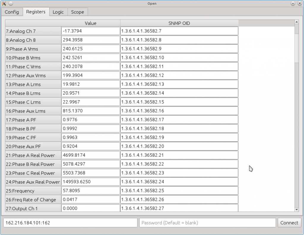
In this screenshot from the configuration assistant we see registers #7 to #27
Register #8 Always contains the current value of input channel 8
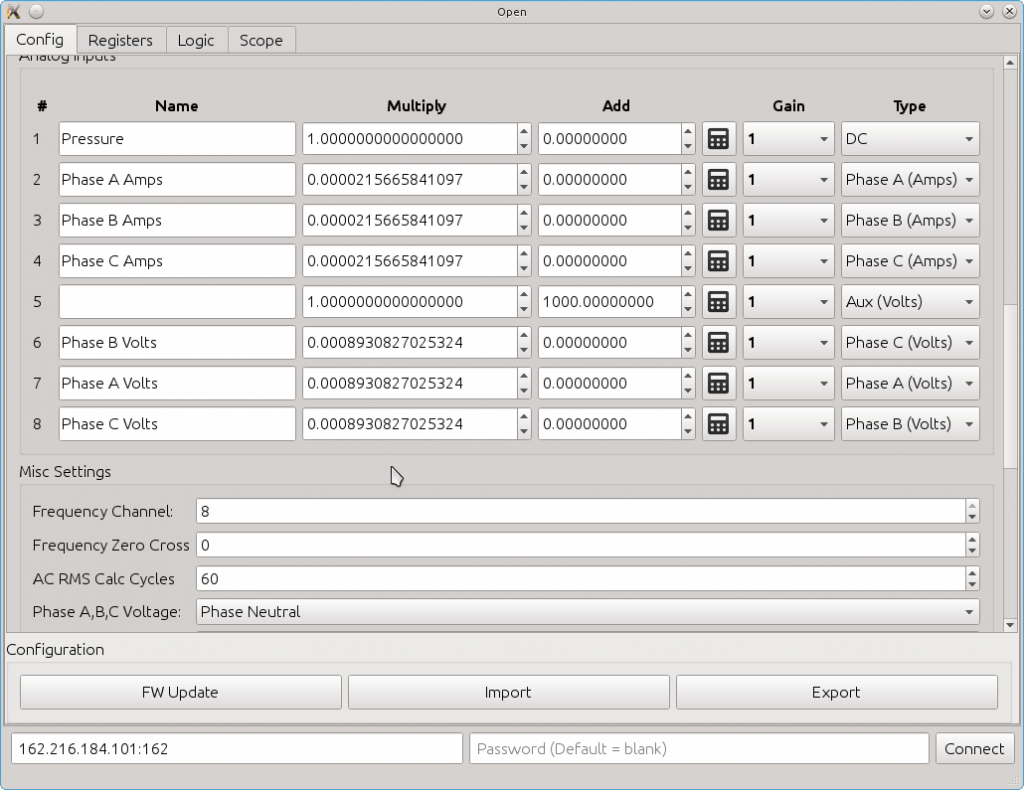
Register #9 Always contains the vRMS of the input configured as Phase A Voltage (See below screenshot)
Register #25 Always contains the frequency of the input channel configured to measure frequency (#8 in our example, see below screenshot under the “misc Settings” group)
Register #13 Always contains the lRMS of the input configured as the source for Phase A Amps and is connected to a Current Transformer
Register #27 Contains the value of Output Relay #1, this register can be read to obtain the current value or written to to set the status of the output relay
Under the “Misc Settings Tab”
- Frequency Channel: The Input Channel selected to calculate frequency on.
- Frequency Zero Cross: Frequency is calculated based on how many times the input goes above and below a fixed threshold, for AC sources this can be set at 0 as this is the midpoint of the waveform, for DC sources it can be set at whatever the midpoint of the input waveform is.
- AC RMS Calc Cycles: How many cycles of data to collect and average before calculating AC metrics. With a setting of ’60’ the AC metrics are updated approximately every second on a 60HZ grid. A setting of 1 would calculate metrics every single cycle.
- Phase A,B,C Voltage: This allows software changing of Phase Neutral voltages to Phase Phase voltages, it should be left in it’s default state unless speciality requirements exist as changing the voltages to Phase Phase will throw off the Watts Calculation and Power Factor calculation.
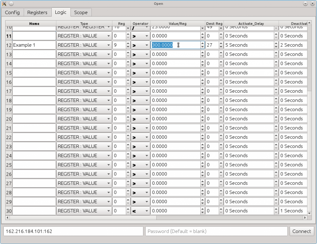
Now lets go back to our example, we want to activate output channel 1 (Register #27) when the Voltage on Phase A (Register #9) exceeds a value of 300 for more than 5 seconds
Going to the ‘Logic’ tab we add an entry for our expression.. We set the type as REGISTER:VALUE as were comparing a register (our voltage) with a value (our threshold)
Next we set the expression to ‘>’ meaning ‘Greater Then’
In the next column we enter our threshold value of 300
so what we have here is an expression that is comparing the value of register #9 with a value of ‘300’; The output of this expression will either be True (1) or False (0).. Lets now direct where to place the output by setting the “Destination Register” to #27 (Output Ch1) Oh, and lets not forget the Activate Delay, setting this to ‘5’ means that the expression has to be ‘true’ for more than 5 seconds before setting the Destination Register.
Now that were finished creating our logic rule click the ‘Upload’ button in the bottom right and output Ch1 will begin reflecting the value of our expression.
Clicking the ‘Upload’ button uploads your configuration to the Flexs Q3 but dose not save them, if you want to save the settings so they are not cleared on a reset click the “Apply Settings” button from the main configuration tab.
That’s how it works, very simple and flexible and we didn’t even go through a fraction of the available expressions.. Registers can be multiplied by other registers. Added to other registers and compared with other registers!


